Archive
Before We lose Track
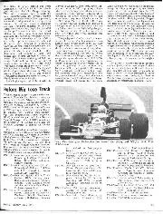
Before We Lose Track THE NAME of Shadow is a comparative newcomer to Formula One, these cars being the products of Nichols Advanced Vehicle Systems Inc., the engineering firm run…
CRANKSHAFT COMPROMISES
rthe earlier days of the internal combustion engine the question of crankshaft design had not attained anything like the importance it has today. This was due to the fact that revolutions per minute were ex tremely low, and as long as the crankshaft was stiff enough to stand
the punches of the burning mixture without breaking, or distorting sufficiently to break the crankcase, it was considered a good design. Some attempt at balance had, of course, to be made, but here the problems were comparatively simple, as the shaft could always be regarded without much error as being rigid. Therefore, if the shaft was in static balance, which can easily be done on knife edges, it was likely to be satisfactory.
Recent developments in the “upper works” of the internal combustion engine, that is in piston, combustion chamber, and valve gear design, in addition to the general introduction of supercharging on racing engines, has pushed the r.p.m. of the modern engine up to such a pitch, combined wi th a very high M.B.P. that the crankshaft has become the governing factor in many engines.
In spite of the way one hears motoring enthusiasts laying down the law about the rights and wrongs of various designs, the problem is far from being as simple as they seem to think. This fact is borne out by the great variation in many designs by different manufacturers who are anything but foolish, and whose products are astoundingly successful. Practically the whole difficulty in crankshaft design lies in the fact that shafts are not rigid and cannot be made so. Therefore, the only course is either to support the shaft in such a manner as
to minimise its contortions,’..or. to make it stiff enough to keep within bounds with the minimum o saipport. All designs are a compromise between these methods, and the elasticity of steel and its deflection under load has caused engine designers much thought and trouble.
The perfect crankshaft is a myth, and while the properties of materials continue as they are now, it is likely to remain so. Thus, although there are almost numberless wrong ways of making crankshafts there is no absolutely right way. Some crankshafts are better than others, and the best are those where designers strike the most
effective compromise in the various problems involved. Having arrived at this depressing conclusion, it is interesting to see the snags in the various types of design, and the way in which they may be, to some ex tent, avoided. Leaving the question of single and twin cylinder en gines for Ethel moment as being unusual in car practice, and taking the normal 4 cylinder shaft as the simplest example, we can consider what happens to it when the engine is running under load. It has two main distortions, consisting of bending and twisting, the latter being the
rotary deflvction of any one crankweb relative to the others.
There are various ways of avoiding each of these, but in general it is true that with similar shaft dimensions, the less it bends the more it twists. The simplest form of shaft is that in Fig. 1, and at high speeds the centrifugal loading due to the rotating portion of the connecting rods, added to the similar loading of the crank webs and journals themselves, will tend to bend the shaft. The bending effect of the two centre journals will be the greatest, and the shaft will tend to deflect as shown by the dotted line in Fig. 2. Twisting is chiefly caused by the fact that each cylinder fires separately, and the one that fires, naturally tries to ” get on with it,” regardless of the others, with the result that in imparting its motion to the whole there is a momentary rotational movement of each web relative to the others. Owing to the elasticity of steel each part of the shaft springs back to its correct shape. If, however, the frequency of the explosions coincides with the natural torsional frequency of the shaft, it will set up greatly amplified vibrations which, apart from being very bad for any auxili
ary drives, such as the camshaft, which are driven from the crankshaft, will probably break the crankshaft by fatigue of the metal.
Fortunately, the natural torsional frequency of a simple shaft is very high and trouble is not likely to come from this source.
From the point of view of bending, it will be obvious that this shaft is not too good, but if the sections of the webs are robust it is fairly satisfactory. Also the freedom from torsional troubles is no mean advantage, and this simple type should not be so utterly and swiftly condemned as it is so often. As the lightest possible conrods have already been assumed to be fitted, the only way of increasing its resistance to bending is to increase its size. This, unfortunately, also increases the weight, which is the cause of the centrifugal weight which causes it to bend. Already the art of compromising is coming into play ! Therefore, the weight must be increased in the right places, i.e., near the centre of the webs, and not too much at the big-end journals, as this will also mean heavier big-ends. Here the compro
mise is chiefly between weight and rate of wear or load factor of the bearings.
In this shaft each big-end and its accompanying reciprocating parts is approximately balanced by its opposite, but off-set, number. It is this ” off-set balancing” which leads to the suggestion that all centrifugal loading troubles can be got over by balancing each big-end and its rod and piston separately by balance weights opposite each web. Reciprocating parts cannot be correctly balanced by rotating parts, as one’s single cylinder experience has pointed out in the past, but it can be done very nearly by placing about 0.6 of the reciprocating weight at crankpin distance from the shaft centre on the opposite side to the crankpin, plus, of course, a weight equal to the rotating weight of the big end. Here some cunning estimation, which need not be gone into here, is required to determine how much of the con-rod is rotating and how much is reciprocating. The result of this is a crankshaft on the lines of Fig. 3, the position of the balance weights for the end and centre journals being shown. This gets over, to some extent, the bending due to centrifugal loading, but as is usual in this world,
brings corresponding disadvantages, apart from extra cost.
The extra web for balancing means that the shaft can no longer be made as a simple drop-forging (as Fig. I can be made), and must be cut from a solid billet. In Fig. I the ” grain ” of the metal will follow the webs and journals of the shaft throughout, making for strength
and toughness, while in Fig. 3 this grain will only follow the journals and will be at right angles to the webs.
This is a fairly minor disadvantage however, and increased safe revs., and consequently more power, will be obtained. In the case of the simple twobearing shaft of Fig. 1, we only mentioned the bending force due to centrifugal loading, as this was the most potent.
Having coped with this and duly increased the power it will be found that the bending forces due to the explosion pressures will become more important and will cause deflection in the shaft due to its considerable unsupported length.
Whereas Fig. 3 obviates only one source of deflection, it would appear that both centrifugal and explosion forces can be simply dealt with by supporting the shaft at its centre, giving a crankshaft of the form of Fig. 4. It also removes the obvious objection to the method of balancing used in Fig. 3, where the balance weights although an improvement, are not correctly opposite to the parts they are supposed to balance, and therefore each producing a local couple between each pair of crankpins.
Although Pig. 4 provides support for the centre of the shaft and so avoids the deflection shown in Pig. 2, the forces are still there as in the simplest shaft of all. This means that the load on the centre main bearing of a 3-bearing shaft without balance weights is excessively high. Even if it does not cause failure it causes loss of power, and therefore balance weights are really just as necessary as in the first case.
This gives us Fig. 5 which has balance weights which will ease the load on the centre bearing, but in this apparently logical development we are steadily increasing the one trouble from which Fig. 1 is comparatively free. That is the chance of torsional vibrations being set up in the shaft. The torsional stiffness of the shaft is mainly governed by the size of the journals, especially the centre main journal.
The character of this is already hinted, as an undue increase in this leads to a dangerously high rubbing speed in the bearing surface, and at very high engine speeds the rubbing becomes the most important consideration.
Adding balance weights, therefore, increases the weight of the shaft while its stiffness remains unaltered. The result is exactly the same as when a spring of fixed strength is loaded with a larger weight. Its natural period of oscillation becomes slower. This means that the natural period of torsional vibration of the shaft is being brought nearer the danger point.
Fig. 5 also suffers from the trouble of the balance weights not being directly opposite the reciprocating parts, and therefore produces local stresses between Nos. 1 and 2, also 3 and 4. It is naturally impossible for the balance weight to be in the same plane as its conrod, but the same effect can almost be obtained by splitting the balance weight and having half on each side of the rod opposite the crankpin. This necessitates a main bearing on each side of each crankpin so that we have a set of single cylinder crankshafts each with its balance weights, joined together to form a complete unit.
This gives us Fig. 6, a 4-cylinder 5bearing shaft with balance weights. Of the possible variety of 4-cylinder shafts this is the best in its freedom from bending, and far the worst in its liability to torsional vibration. All crankshafts are a compromise between the types suggested, and it is not correct to condemn a crankshaft because it has few main bearings. A multiplicity of bearings is no merit in itself, but only in so far as the undesirable complication, length, weight, and expense, which they entail, is compensated for by improvements in other directions. We have only so far considered the four-cylinder type as it sets out the problems involved. Actual engine balance except in so far as it directly affects the crankshaft has not been mentioned, and it is far too big a subject to be in
eluded as a side line. It is sufficient to note that owing to the fact that in a 4-cylinder engine the pistons going up do not correctly balance those coming down, and that a six-cylinder engine is much better in general balance. Owing to its lighter reciprocating parts in an engine of the same capacity with only four cylinders, the possible r.p.m. are higher.
As far as the actual crankshaft of the ” six ” is concerned the same problems occur as in the “four,” only the torsional difficulties are greater owing to the greater length of the shaft.
If the shaft has the full number of bearings (seven in this case), the tendency to twist will be considerable and if made with heavy crank webs and small journals it will almost certainly break from torsional vibration if racing speeds are attempted. Apart from this it will be rough at ordinary speeds.
The moment of inertia of the shaft can be kept down, and its resistance to twist kept up, if the main journals are kept as large as possible consistent with their other limiting factors, and the crankwebs kept comparatively thin, though broad, viewed from the end of the shaft. Another point to be considered is the question of the flywheel, which is usually mounted on the rear end of the crankshaft and the auxiliary drives taken from the other end. This gives the worst possible
combination, for if the flywheel is heavy, that end of the crankshaft will rotate at an even speed, while all uneven angular movement will be greater at the front end, so causing chatter and excessive wear on the camshaft and other drives. If a flywheel is required at all, the correct place for it is the centre of the crankshaft, with the camshaft drive taken from the same spot, but this is a complicated and expensive method of construction.
Actually, in racing or even fast touring with a smooth engine of six or more cylinders, a flywheel is superfluous and undesirable. The modern stiff and heavy crank shaft is a flywheel in itself, and as long as some plate is mounted on the crankshaft of sufficient strength and rigidity to carry the clutch, no more is required.
When one considers the nu merous limitations with which the des igner is faced in designing an engine, such as overall dimensions, wei ght, and especially cost, it will be seen that crankshafts are no mean problem, ev en from the point of view of shape. In add Won to this we have to thank the metallurgical experts who have produced steels capable of standing the terrific stresses imposed, so that instead of calmly telling the maker of our particular car just how he should build his engine (as so many do) we might well be thankful that it goes as well as it does.