Archive
Aston Martin Vantage rolls into new GT3 era
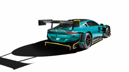
What a beast. This is the new Aston Martin Vantage GT3 upon which Britain’s great sports car maker has pinned its hopes for a bountiful season in the super-competitive category,…
A One-Piece Metal Hull.
LOW WEIGHT AND SIMPLICITY AlMED AT IN UNCONVEN7 ZONAL DESIGN.
AN interesting departure from orthodox boat construction is shown in a hull designed by Mr. Villa Gilbert, who is well-known as a pioneer both of aviation and of the production of heat treated steels.
The principal features of his design lie in simplicity and cheapness though the attendant graces of lightness and robustness are also considerably in evidence. The hull is made in one piece from a single rectangular sheet of metal, first curved so as to form a semicylindrical trough, and then pressed into a transverse dent near the middle. The forward. end is then drawn to a vertical edge to form the cutwater, and is welded up, and the stern closed with a welded-in metal plate forming the transom. The gunwale is formed either by rolling over the edges of the metal to form a lip, or by reinforcing the edge with a metal or wooden strip. In the original form which was intended primarily for a small dinghy, the bow and stern were identical, and the hump or dent formed the seat, but for faster moving boats the square stern is generally supposed to be the more efficient shape.
Sketches 1, 2 and 3 show clearly the general form of the hull, and though these diagrams are not necessarily to scale, the proportion will ordinarily come fairly near to those shown. As already stated the original idea was to use this form of construction for small dinghies, and it was shown that a 7 foot boat 3 feet wide, in aluminium would weigh only 151bs., and would cost little over two pounds to make.
One or two small models made by the writer, in. thin sheet metal, indicate that a surprising degree of rigidity, both in bending and torsion, results from this shape, while the absence of biplanar curves does away with the need for elaborate press tools or dies.
Turning to the question of applying this method of construction to light speedboats, our first concern is to know how the hull will ride at speeds of 30 to 40 miles per hour. Unfortunately there are no definite data to hand, either for full scale trials or model tests, so one must look only to theory for information, exercising proper caution in view of the unconventional forms of the immersed bodies. Considering first the static stability, it is evident that the flatter cross section of the after part will, by increasing its displacement, enable most of the weight to be placed aft, as is usually required with outboards. Lateral stability appears from the model to be good if the hull is fairly wide, though the double ended hull had a tendency to roll unless deeply immersed. Calculation of the metacentric heights may well be left to some very idle mathematician, and experiment would be tedious in view of the infinite variety of shapes produced by altering the shape of the transom piece from a vertical line almost to a horizontal line. A rectangular transom about equal in width to the
” dent ” seems to give the most satisfactory shape to the after section, though it would be extremely interesting to study the performance of a hull with a vertical knife edge stern under high speed conditions.
Treating the boat so constructed purely as a displacement vessel, the form would not appear by any means ideal, one’s first impression being that considerable eddying might be set up between the two sections. Further, when one comes to consider the waterline plan, and the other sections parallel thereto, one grows very dubious as to the performance at high speeds.
Fig. 4 indicates the approximate waterline plan of the square stern variety, but it must be borne in mind that the sides are inclined outwards and upwards at small angles to the water surface, so that the streamline displacement is by no means as abrupt as would appear from this figure. In fact, considered alone, the after section offers a very good form, owing to the small angles of incidence and smooth contours.
One’s doubts remain, however, centered on the forward body, as its fairly deeply immersed and wedgelike form certainly appears likely to set up diverging waves, While the down pull due to the upward sweep of the back of this section, although making for excellent steadiness and controllability, may result in considerable loss of power. It is possible that much of
this power may be recovered in the form of lift on the afterbody, though the changes of direction of the slipstreams are certain to involve a certain amount of waste of energy.
Calculation is difficult where inclined curved surfaces are concerned, but it is fairly evident that • all the “paths of minimum curvature” backward from the cutwater, end in an inward and upward curve too sharp for eddyless motion at 30m.p.h. for instance. Only experiment can show the extent and relative importance of these possible causes of power loss, and to judge from the flexibility of the design, such experiment should not prove either difficult or costly to carry out.
For the rest, steering should be good, probably better than in ordinary skimmer hulls as the semi-displacement type is much less prone to skidding and the deep cutwater would maintain a steady course. Fairing of the upper part of the boat, in addition to being easily carried out, should give a good shape so far as air resistance is concerned, particularly if it is taken into consideration when the metal hull is being constructed.
In this connection it has also been suggested that such hulls would be very suitable for seaplane floats, and flying boats, both on the score of rigidity and lightness and good aerodynamic characteristics.
However, the very feature which renders them stable on water, namely the down pull of the forward body might seriously impede rising off the water, and the lack of lift of the forward part would tend to “trip up” the aircraft when descending steeply onto the water.
It is reasonable to suppose that some modification of this design incorporating an outward flare of the bows might rectify this objection.
It is understood that hulls of this type are shortly to be produced on. a commercial scale, in sizes up to some 12 or 14 feet in. length, suitable for carrying outboard engines, and one looks forward to seeing the early practical application of this very interesting and original type of boat. (The designer and patentee is Mr. W. Villa Gilbert, c/o Institute of Patentees, Victoria Street.)
R. R.. POOL, B.Sc.