Secrets of the Lotus 18
Colin Chapman stole a march through emerging technologies with the Lotus 18

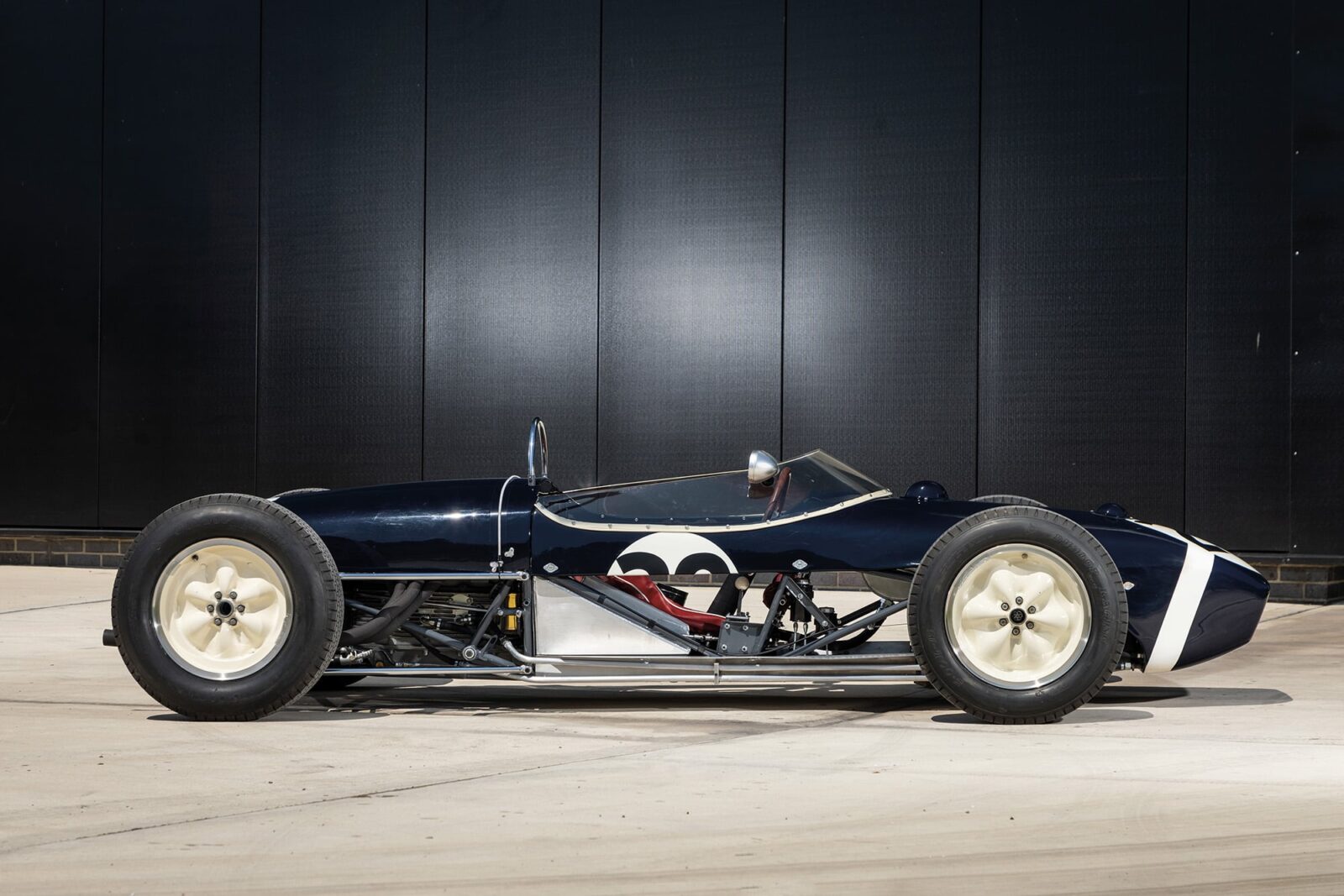
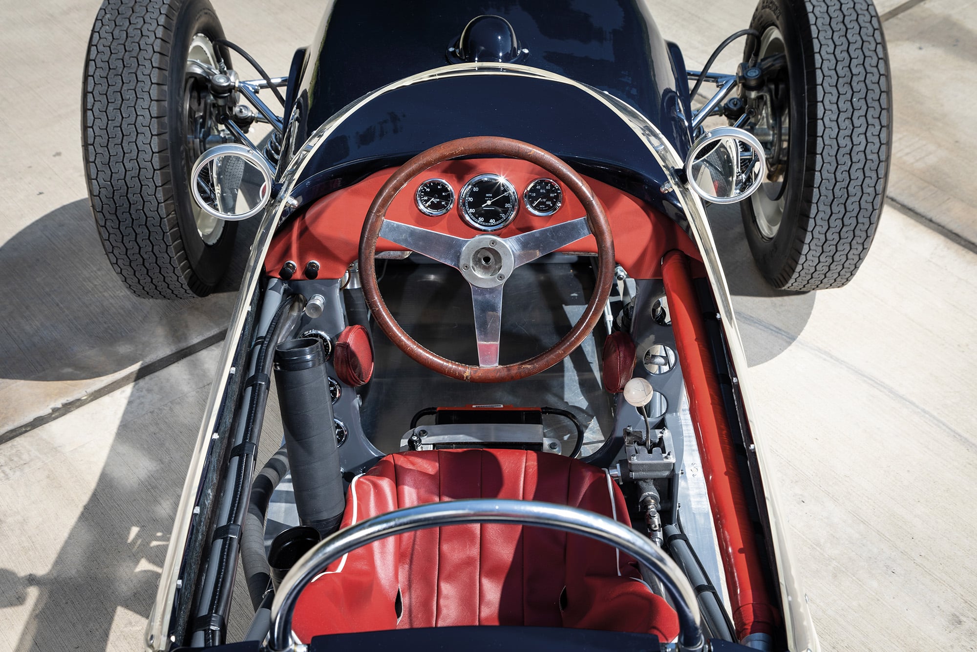
The Monaco-winning 1961 Lotus 18 is up for sale after a painstaking restoration by Classic Team Lotus in 2019
The Lotus 18 – introduced to F1 in 2.5-litre form in 1960 – represented Colin Chapman’s acceptance that the Cooper format of placing the engine behind the driver was the correct one. This was a more scientifically informed version of that concept. The details explained here made it more grippy than the Cooper, but it demanded a subtly different driving technique that only amplified the difference between Moss and the rest.
Chapman’s overarching aim was to maximise the grip of the tyres. Considerable advances had been made in tyre technology in the latter half of the 1950s, resulting in tyres that performed at their peak at lower slip angles than before. But the design of the cars had not evolved to incorporate that change and still featured constructions and suspensions that dictated old-style slip angles. With the 18, Chapman addressed this.

Rigid spaceframe and novel suspension gave 18 superior grip
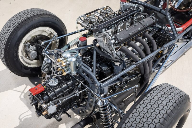
Stiffness of chassis and suspension mounting was key to ensuring the suspension worked the tyres in the desired way. Like all F1 cars of the time the Lotus chassis comprised a multi-tubular steel framework, but unlike those of the Cooper (and the Cooper-like Ferrari 156 chassis) these were arranged to form a spaceframe. The distinction between them is that structurally a spaceframe forms a single entity when loaded. The tubes are all straight, arranged in straight lines and triangulated, ensuring loads are spread equally over the whole structure and not into any single joint.
The Ferrari chassis was simply multi-tubular, but with curves to clear components and without a geometry that would spread the loads. It could be made nowhere near as stiff.
Chapman reversed the suspension wishbones (now a commonplace arrangement) with the apex of the two arms on the inside and the wider- spaced bases outboard. He also added a radius rod from the rear bottom wishbone to a point just behind the cockpit, bracing the suspension and further controlling the wheel angles. Combined, this was a vastly stiffer arrangement and allowed the 18 to more instantly load up into a static cornering state and to hold the modern tyres much closer to the narrower slip angle for which they’d been designed. Lateral weight transfer was reduced, and even under maximum roll the geometry dictated that the outer rear wheel remain fully upright.

