Archive
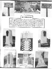
Obituary -- Cliff Davis
With regret, we record the passing of Cliff Davis at his London home, aged 68. Generally described as the 'flamboyant Cliff Davis', he was a motor trader specialising in American…
TUNING THE BLACKBURNE SUPER-SPORTS 350 C.C. ENGINE. By!. P. RIDDOCH.
APPRECIATING the keenness of many motor cyclists to be able to purchase at a reasonable price the most up to date racing engine, Burney & Blackburne, Ltd. decided to produce for this season a new model O.H.V. engine with double exhaust port, possessing all the very latest improvements and features of design.
Though the engine in standard trim is capable of a very competitive performance, it is, however, of course possible by various ways and means to ” boost ” the engine such that the machine in which it is fitted, stripped for racing and ridden solo, may be capable of exceeding 90 m.p.h. It is hoped therefore, that the following notes will be of assistance to owners of these engines who intend to go in for racing.
The engine itself closely resembles the 1926 T.T.
engine which put up the extraordinary record of obtaining five places out of a possible nine (1st, 2nd, or 3rd) in the T.T. Races, and was the only 350 c.c. engine that has ever held the hour record in the 500 c.c. class, and recently won the 200 miles sidecar race Class B. at record speed. In so far as the crankcase and crankshaft assembly
are concerned, there is very little which requires to be done to improve the engine’s performance. The sinall end of the connecting rod may be lightened and polished, but under no circumstances should the rod be drilled : it is much more important that the rod should be rigid than exceptionally light. The exhaust lifter may be dispensed with and the arm of the exhaust rocker upon which the exhaust lifter cam works may be ground off, thereby lightening the exhaust rocker very considerably. The pads of both rockers operating against the ends of the tappets may be reduced ; the ends of the tappets should be smeared with blue or other paint so as to mark the bearing surface required on the pad of the rocker, and superfluous metal may be ground away. The cylinder should be carefully lapped and polished
with metal polish, using a scrap piston and an old pair of rings. The head, without valves, should be placed in position on the cylinder and the joint between the cylinder and the head inside should be carefully examined through the ports and the bore of the cylinder, and any ridge, either in the head or the cylinder, should be removed by filing, while the joint faces should be blended together as carefully as possible. The copper gasket washer between the cylinder head
and the cylinder may be discarded and the head ground direct on to the cylinder barrel : when assembling the head on to the cylinder some heat resisting jointing compound, such as Firmantite, should be smeared upon the joint faces. The combustion chamber and both valve ports are fettled and polished by the manufacturers. It is, however, possible still further to improve the performance of the engine by removing still more metal from the inside of the ports so as to make the passage for the gases
as smooth and stream-lined as possible. The inlet valve guide may be cut off flush with the inside of the inlet port. On no account, however, must the exhaust valve guide be shortened. The joints between the choke of the carburetter and the inlet stub, and again between the inlet stub and the inlet port on the cylinder head must be blended together perfectly and should be polished smooth.
The valves should be ground in with fine grinding paste and finally with metal polish. The seating both on the valve and in the cylinder head may be adjusted to a width of about 1j16 in. for the inlet valve and 3/32 in. for the exhaust valve. A light tulip-shaped inlet valve can be obtained from the makers for short distance racing.
Should there be any indication that the valve stems are too tight a fit in the valve guides, such as seizure marks, such marks should be removed by polishing with fine emery cloth until the valve works freely in the guide. If the valve stem is too tight a fit in the guide, a considerable drop in power will be experienced. The lift of each valve is 5/16 in.
If at any time new springs or new valve guides are fitted the maximum lift of the valve should be checked over : it should be possible to lift the exhaust valve 7/16 in. and the inlet valve 7/16 in. before either the top of the valve collar comes in contact with the top of the valve guide, or before the coils of the springs are completely closed up one upon another.
This is an important point and should be carefully checked whenever new parts are fitted. The inner spring on the inlet valve often requires to be slightly shortened to give the full 11/32 in. lift.
The valve springs supplied upon the engine are suitable for fast touring and long distance racing : for sprint races where high speeds may be called for, extra strong and long inner and outer valve springs can be purchased, in conjunction with which it is necessary to use a special type of top valve collar. These special springs have an open coil at one end.
The two ring aluminium alloy piston fitted in the engine gives a compression ratio of just over 6 to 1: the ration may be increased to 8 to 1, by discarding the copper washer and by shortening the cylinder 1/16 in. This should be taken off the top joint face and the register in the top of the barrel of the cylinder head must be deepened by a corresponding amount. A single ring sprint piston can be obtained which will still further raise the ratio to 8i to 1 : the manufacturers recommend that this piston be only used for short distance events with alcohol fuel. If, however, the temperature of the engine is suitably controlled by proper attention to the mixture and ignition settings, it will be found quite safe to use the piston for long distance racing as well. When using a high compression ratio either with the two or single ring piston, great care must be taken to see that there is adequate clearance between both valves
and the top of the piston : when the piston is on to dead centre and both valves are closed it should be possible to lift either valve off its seating 3/16 in. before coming into contact with the top of the piston. If necessary, flats may be filed on the top of the piston opposite the valves in order to allow sufficient clearance. The actual amount of clearance may of course easily be checked by mounting the head complete with valves on the cylinder assembled, but without valve springs and collars.
Under no circumstances should the piston be drilled nor is it desirable to reduce the bearing surface of the piston on the cylinder wall : the latter practice will prevent conduction of heat from the piston to the cylinder and therefore cause distortion and local seizure of the piston.
The piston rings should be lapped into the cylinder with metal polish and must show good contact all round. The gap at the joint should be from .004 in. to .006 in.
The best valve setting for both short and long distance racing will be automatically obtained if the instructions given in the makers’ instruction booklet are correctly carried out. The tappets should be adjusted as closely as possible so that the push rods can only just be freely turned, and the valve timing should then be set such that the inlet valve commences to open two fifths of the total overlap before top dead centre. Before finally checking the setting it is necessary to assemble the timing case cover on the engine so that the camwheel is supported on both sides : the absence of the timing’ cover will cause a discrepancy in the valve timing owing to the camwheel, under such conditions, being supported in one bearing only.
Before completing the assembly of the engine a careful test should be made to see that all moving parts move quite freely. This should be done with the cylinder and piston head butt/ without piston rings. The clearance between the timing main shaft and its bearing may be increased to .004 of an inch for racing. The timing gear must work freely in its bearings and the alignment of the piston in the cylinder bore should be carefully checked. The magneto setting should be adjusted so that when the contact breaker is fully advanced the points commence to break 38° before top dead centre. The correct amount of advance will vary inversely to the performance of the engine, i.e., the better the performance of the engine, the less advance will the engine take ; some of the fastest engines have given their best results with not more than 30/ 32° advance. If, by experiment, you find that the performance of your engine is improved by giving more than 35/38° advance, it is reasonable to assume that there is some other mal-adjustment, often indifferent carburation, which is handicapping the performance of the engine and allowing it therefore to take more ignition advance than might otherwise be expected, and this mal-adjustment should be sought for immediately. It must be remembered that too much advance will cause not only reduction in speed, but also overheating, burning of the sparking plug, and as a result, possibly serious damage to the engine. Upon a high efficiency engine of this character it must be appreciated
that the control of the ignition is of vital importance.
In regard to carburation the Amac instrument is used, and for road racing and events where acceleration is of primary importance, a choke size diameter 29/32 in. is recommended. For sheer maximum speed an advantage will be obtained by using a 31/32 in. diameter choke. It is impossible to lay down any definite ruling in regard to the size of jet required : this adjustment must be determined by experiment and may require alteration to suit varying climatic conditions, etc. That jet should be selected which is found to give best results with the mixture control lever set midway between these two extreme points, so that there is a 50% variation, rich or weak, available. In carrying out experiments with a view to finding the correct jet it is advisable to start with a jet too large rather than too small. Whereas a rich mixture may have no adverse effect upon the engine at all, a weak mixture will, however, definitely cause overheating and serious damage may follow. For the sake of the engine, therefore, it is desirable that you should commence with a jet too large and work down to the correct size.
The importance of mixture control cannot be too strongly stressed : there are probably more races lost, and more engines ruined or seriously damaged, through being rim on too weak a mixture, than through any other cause. There can be no doubt that a weak mixture has been fundamentally responsible for a great many cases of engine failure, for which some other part has been unjustly and incorrectly blamed.
The manufacturers of the engine have well equipped experimental and racing departments under the supervision of the chief designer. They are at all times glad to give information and advice to owners of Blackburne engines upon their tuning and adjustment.