It’s one of the great mysteries of modern racing: how does traction control work? We tell you how, with a little help from MotoGP electronics providers Magneti Marelli
Until last season the workings of MotoGP rider aids were unknown because the factories kept them a closely guarded secret. But the introduction of control software for the 2016 MotoGP championship changed all that.
Last summer all I had to do was walk into the Magneti Marelli truck and ask to see some data traces that would help me understand how MotoGP traction control, wheelie control, engine-braking control and launch control do their jobs. Vicente Pechuan-Vilar and Maurizio Scrignari at Magneti Marelli were only too happy to help, although they may have changed their minds when I took up hours of their time asking one stupid question after another.
After Magneti, I needed to speak to someone to get the rider’s point of view. I chose Bradley Smith, partly because he speaks my language but mainly because he is one of few riders who is good at articulating his thoughts and willing to spend his time doing so.
This is first of several blogs we will publish over the next few weeks to give you a basic understanding of how each type of rider aid works. Hopefully the knowledge will help you to enjoy watching MotoGP even more.
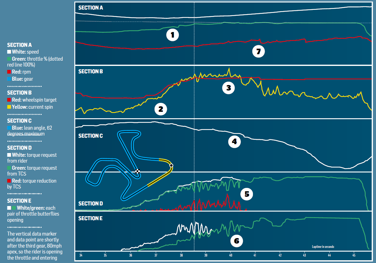
Don’t be freaked out by the rainbow of squiggly lines in the data graph (below). Simply link the numbers in the graph to the numbers in the text, ignoring everything else for the moment, and it should all make sense. Although this is genuine Magneti Marelli data from a hot lap during the 2016 Jerez GP, we don’t know the rider and we don’t know the bike; that’s all top secret.
The first thing to understand about MotoGP’s unified software is that it is significantly lower-tech than the factory kit it replaced. Dorna’s plan was to reduce electronics costs and also reduce their use as a performance aid.
So riders now ride the bike more than they did before 2016, as Smith explains: “We do a lot more now – we tame the engine with the throttle more than with the traction control. Before the unified software, when I used to open or close the throttle the electronics would say, let us do it! Now I’ve got a real connection with the rear tyre. It’s good because the electronics are there for safety, not so much for performance.”
To make sense of the graph, this is turn five at Jerez, otherwise known as Sito Pons corner, the medium-fast right-hander that leads into the downhill plunge onto the back straight. The graph covers the yellow zone on the circuit map, with the dotted vertical line and data point shortly after the third gear, 80mph apex, so the rider is opening the throttle and entering the wheelspin zone, then shifting to fourth and fifth as he accelerates down the starught.
1
Section A: green line is percentage throttle opening. Dotted red line is 100% throttle
The rider is opening the throttle in ‘steps’: he applies more gas, then feathers the throttle by between two and 10 per cent as he feels the tyre spin. When the tyre regains grip he applies more gas, then feathers again and so on. He didn’t need to do this with last year’s more sophisticated factory TCS, which would’ve done it all for him.
2
Section B: red line is spin target. Yellow line is current spin. Blue is lean angle
When the bike starts to lift from full lean the spin target is very low: zero to two per cent (greater than bike speed), depending on rider preference. As the rider raises the bike to exit the corner the spin target increases because the rear tyre and the rider can cope with more spin. Most riders allow the TCS to give a maximum of 12 to 15 per cent spin on corner exit (% difference of rear wheel speed over bike speed).
3
Section B: red line is spin target. Yellow is current spin
Here is the biggest spike in wheelspin, where the rider is accelerating hard and the rear tyre spins much more than he wants. See (5) and (6) to understand how the TCS reacts to this spike.
4
Section C: blue line is lean angle
Note how the lean angle stays steady as a result of the spike in wheelspin – the rider is busy dealing with the slide and momentarily stops adjusting lean angle.
5
Section D: White line is torque requested by rider via throttle. Green is torque delivery from TCS, according to spin. Red shows torque reduction by TCS
The white line shows the rider getting greedy with the throttle, causing a spike in wheelspin (3), which demands urgent action from the TCS, which reduces torque delivered to the rear tyre. The green line is the red line subtracted from the white line and shows the actual torque delivered. Note that the rider doesn’t shut the throttle, because he’s got the bike upright enough and he knows the TCS is helping him out. The TCS is controlled by various parameters and reduces wheelspin in three ways: by closing the throttle butterflies and/or retarding the ignition and/or cutting sparks from one or more cylinders. TCS works at its maximum from 60 to 40 degrees of lean.
6
Section D: white line is one pair of throttle butterflies. Green is the other
In the early stages of corner exit the green and white lines are separate because the two pairs of throttle butterflies are out of synch – they open asymmetrically for smoother power delivery. Many teams map one pair of throttle bodies directly to the throttle, so the rider has a direct connection to the rear tyre, while the other pair of throttle bodies does what it’s told by the TCS. At the earliest throttle opening the TCS may reduce torque by 50 per cent, perhaps from eight horsepower to four horsepower. Closing the throttle butterflies is the smoothest way to reduce torque but it’s not enough in panic situations, when ignition retard and spark cuts reduce torque much more quickly. Ignition retard makes the engine groan; spark cuts give a machine-gun stutter. Some riders like the cuts to tell them the TCS is working, but the cuts can cause suspension pump that upset the bike. Finally, as the rider lifts the bike out of the corner both pairs of butterflies once again work in parallel, because power delivery is now more important than sensitivity.
7
Section A: red line is rpm. Blue is gear position
The rider shifts to fourth and then two seconds later to fifth, the revs dropping slightly with each shift.
Bradley Smith on TCS
“The TCS is a lot more basic now, with a lot more fixed numbers and set values, so we can’t pinpoint the TCS corner by corner to work stronger or weaker. For example, before we could play a lot with the initial touch of the throttle – we could delay the TCS by five metres so you could pivot the bike on the rear tyre with the first touch of the throttle. Now the TCS doesn’t allow that finesse. Before we could go from 30 percent throttle to wide open and the TCS was that sophisticated it would sort everything out. Now if you go wide open to maximum torque request you’ll go sideways; the TCS is only there for when you go way too far, then it’ll catch you. That’s why the throttle trace on this graph shows the rider building torque, spinning the tyre, holding the throttle steady, then when he feels some grip he goes again. Now the riders are taking control and managing it themselves, so the TCS is mainly there for safety, not so much for performance.”