Page 3
EDITORIAL NOTES., January 1927
EDITORIAL NOTES. Ramblings, Rumours and Reminiscences. Being Asides About All Sorts of Things. Is it possible for motor repair work…
EDITORIAL NOTES. Ramblings, Rumours and Reminiscences. Being Asides About All Sorts of Things. Is it possible for motor repair work…
CONTENTS. Editorial Notes ... .•. ... ••• ••• ... 203-204 The " Napier-Campbell" Racing Car ••• 205-206, 210 Motor Racing…
THE " NAPIER CAMPBELL" RACING CAR. Details of Capt. Malcolm Campbell's 450 h.p. New Chassis. A T the time of…
MOTOR RACING PROSPECTS FOR 1927. By E. K. H. KARSLAKE. THIS year there will be five races which count for…
HOW WE WENT TO GLOUCESTER WITH THE N.W.L.M.C. By ".JONAH." AT least that is where we thought we were going—…
MOTOR CYCLE RACING AT BROOKLANDS DURING 1926. Two interesting booklets have just been issued by the B.M.C.R.C. to its members—a…
SPORTING CARS ON TEST: THE " TWO-LITRE " BALLOT. By RICHARD TWELVETREES. THE fact that the Two-Litre Ballot, I tested…
MOTORING SPORTSMEN. Mr. John Donald Barclay. By THE Forrok. THE photograph reproduced at the head of this article will be…
A TWO-STROKE BOOM? Is there to be a two-stroke boom ? The answer is that there is every probability of…
SPORTING MACHINES ON TEST: The 350 cc. Harley-Davidson. "THE RABBIT." RFADERS may look askance at the photographs of this machine…
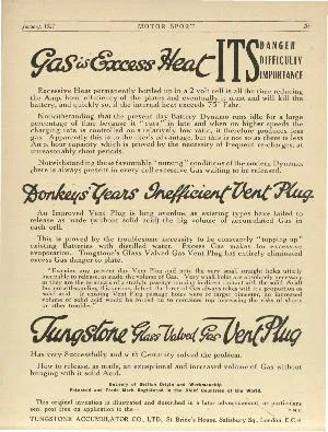
TUNING CARBURETTORS FOR COMPETITION EVENTS. The " Solex " Carburettor. THE " Solex " carburettor occupies a deservedly popular place…
THE BRIGHTON RACE TRACK. A new track, of which the salient features are made clear in the above plan, is…
THE LONDON-EXETER RELIABILITY TRIAL. Well Supported by Amateurs The Winter Classic proves a Great Success. FOR the habitual trials enthusiast,…
INTERNATIONAL CAR RECORDS. 1,i) to 15th November, 1926, (New International Distances.) WORLD'S. Records made at Brooklands unless otherwise stated.
Round the Clubs HONORARY DISTRICT AGENTS. Honorary District Agents are appointed by " Motor Sport" to further the interest in…
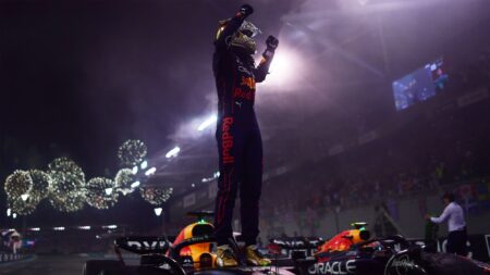
Max Verstappen gave a final demonstration of his overwhelming dominance in 2022 with victory in the 2022 Abu Dhabi Grand Prix, but Sergio Perez lost second place in the championship to Charles Leclerc — as Sebastian Vettel bowed out

Sauber principal Jonathan Wheatley says the aftermath of Gabriel Bortoleto's huge Interlagos shunt showed how far the team has progressed
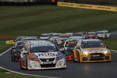
After the British Touring Car Championship finale at Brands Hatch produced a thrilling conclusion, Andrew Frankel explains why Formula 1 should be taking note Photo: Motorsport Images I think we’re actually…
Next week, Imola will kick off the European season and a triple-header that will be key for teams and drivers who want to start easing the pressure after a difficult first part of the year