Archive
Advice Required
Sir, Liking cars of character but being of relatively slender means, I am contemplating acquiring a Rover P4. Unfortunately, I am experiencing some difficulty in obtaining the necessary information relating…
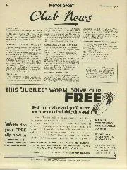
NOVEL OILING SYSTEM ON RUDGE T.T. MACHINES.
THE Rudge T.T. Machines thitiesyear will have
ofquite dry-sump lubrication anovel order.
A worm driven double-acting pump working vertically in a pair of bushes in the timing case draws oil from a saddle pillar tank and delivers it via the main shaft through a hole drilled in the off-side flywheel to the big-end. In order not to weaken the crankpin the usual practice of drilling it has not been adopted, but instead the oil finds its way to the bearing surfaces through a groove cut on the circumference of the pin. A by-pass takes about one-sixth of the oil supply and delivers it to the rear cylinder wall. A scraper at the back of the crankcase removes the oil from the flywheel and drops it into a sump situated below and behind the crankcase, from whence it is drawn up through a channel in the wall of the crankcase and through the timing case to the top end of the sump. It is thence discharged back into the oil tank. The whole assembly is extremely neat, and at a casual glance it is difficult to distinguish the T.T. system from the standard, as there are only three external pipes, and the appearance of the timing case has hardly been altered. In addition, the fact that the sump is situated at the rear of the crankcase has not necessitated any sacrifice of ground clearance. The general design of the T.T. machines will follow closely on the lines of the standard Ulster model. The wheelbase has, however, been lengthened by 11/4 inches. All the well-known features will be retained, including the four overhead valves, four speed gear, and interconnected brakes. Gear operation has been entirely altered, the control be
ing by foot throughout. Every time the double pedal is pressed forward a higher gear is engaged, while a backward pressure engages the lower gears. In the brakes also there has been a slight change, for duralumin anchor plates have replaced the usual steel plates.
A Y alloy slipper piston will be used, giving a compression ratio of 71/4 to I , and there has been a change in the cylinder design, in that the base is held to the crank case by six studs passing through a remarkably heavy circular flange. Following Ulster model practice, the drive side of the crank case is heavily webbed, and contains both roller and ball races for the crankshaft. There is also a roller race on the timing side, and the big end contains a caged bearing with long rollers of -Ain. diameter. Shock absorber details have not yet been finally settled, but the steering damper will be controlled by a hand lever.