Page 3
The Way of Things
gite A).:Great Feat; IN flying from England to Australia in nineteen days Miss Amy Johnson has accomplished a feat which…
gite A).:Great Feat; IN flying from England to Australia in nineteen days Miss Amy Johnson has accomplished a feat which…
UNCILANU 1.0 AUSTIPAILIA IDAUTICUILAIPS CU AM1Y JCIFINSON'S CILEAT FIICLIL THERE have been several flights to Australia during the past few…
ITALY REGAINS THE TARGA FLORIO Varzi, on an Alfa-Romeo, wins by a narrow margin. Buciattis second and third. FIVE years…
AN ATTEMPT TO PEEP INTO THE FUTURE RACING cars are of so many categories that it is necessary before entering…
THE ALVIS SPORTS "SILVER EAGLE. THE actual car tested by 1110TOR SPORT was the same vehicle that had earlier in…
CONTINENTAL RACING NEWS THE GRANDS PRIX OF ORAN A Double Bugatti Victory Results of the racing car event : 1.…
SIX DAYS IN SCOTLAND Some Experiences of an Amateur in his First "Scottish." IT is a cynical saying that anticipation…
ELLAN VANNI A SPORTSMA A 'S PARADISE By " ISLANDER N Spring the young man's fancy turns to thoughts of…
MEN & MACHINES IN THE ISLAND SOME NOTES ON THE 1930 TOURIST TROPHY. EACH year as T.T. machines make their…
etiJ /Lewd' SOUTH-MIDLAND CENTRE CHAMPIONSHIP TRIAL. SAtirday, July 12th, is the date chosen for this event, which will be open…
For any further information you require, please write to Department MS/PR" THE PYRENE COMPANY, LIMITED, GREAT WEST RD., BRENTFORE1, MIDDLESEX…
FIRE REGULATIONS FOR CAR OWNERS THE PETROLEUM SPIRIT REGULATIONS STATUTORY RULES and ORDERS No. 952 YOUR CAR TANK IS A…
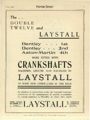
A "DOUBLE TWELVE" M.G. MIDGET ON THE ROAD. WHEN a make of car at its first appearance in a big…
THE J.C.C. DOUBLE TWELVE WELL ORGANISED EVENT PROVES A TRIUMPH FOR BRITISH CARS THIS year's Double Twelve was chiefly remarkable…
The AUSTIN `SEV N' gives most for your money THE outstanding dependability of the Austin Seven and its remarkable value…
to be re-metalled, and later in the afternoon reassembled the engine and got going again just before the end of…
THE ENTRIES FOR LE MANS THE entry lists for the famous Grand Prix d'Endurance, to be run at le Mans…
TUT CLAMP [DUI% CIF Bugattis fill First Three Places. Results of the final handicap : 1. Etancelin (2,300 c.c. Bugatti)…
A THOROUGHBRED WITH A HISTORY For more than a Decade, Road and Track Racing has been the Arduous School through…
A New Trainer. The D.W.2 with Cirrus Mark III. Engine. ADISTINCT breakaway from the conventional is represented in the D.W.2.,…
He's Brazil's all-time leading goalscorer, a three-time World Cup winner and widely acclaimed as the greatest footballer of all time. But for many F1 fans, the mention of Pele immediately…
If ever concrete proof was needed that Netflix’s Drive to Survive series has vastly impacted F1’s popularity in the USA, you only needed note the 120,000-plus spectators who flocked into…
Two-time Indy 500 winner Juan Pablo Montoya will get behind the wheel of a McLaren IndyCar for his seventh start in the American classic
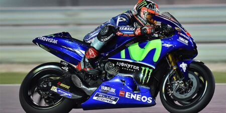
MotoGP returns this weekend in Doha for the opening round of the 2017 season, and so too does 'Ask Mat' Post-season saw a merry-go-round of riders, with only Honda's line-up…